
Technology

Inside the electric jet system.

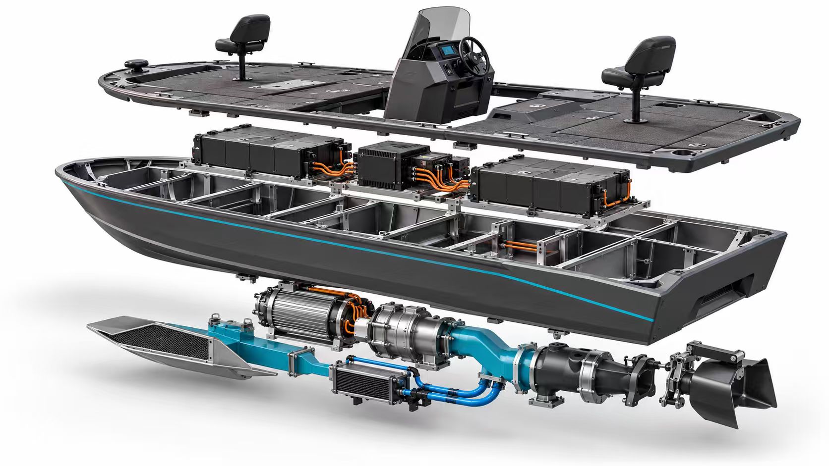
See how the fishing deck, hull, battery, controls and propulsion system come together in one integrated boat.

Inside the system

One boat.
Every layer connected.

Explore the complete electric-jet architecture, from the casting deck to the propulsion system beneath it. Follow the numbered components to see what each part does and how it fits into the whole.

Exploded system view · Select a number to explore.View full image (opens in a new tab)

Components are separated to show their relationship. The illustration explains the system layout; final components and specifications are confirmed in your build sheet.

01 / Energy path

From battery to rotation.

  1. Battery
  2. Controller
  3. Motor
  4. Pump

Stored electrical energy becomes the mechanical power that drives the waterjet.

02 / Water path

From water flow to movement.

  1. Intake
  2. Impeller
  3. Nozzle
  4. Thrust

The pump accelerates water. The outlet and reverse deflector direct it to move and steer the boat.

Upper layer

Deck & helm

The fishing space above the engineering.

The upper assembly brings the forward and aft casting decks, pedestal seats, storage hatches and central helm into one layout. The windscreen, wheel and display sit together at the console, leaving the fishing platforms at either end of the boat.

The exploded view lifts the deck away to reveal the equipment below. In the assembled boat, access is through the designated hatches and service openings.

Back to the full diagram

Below the deck

Battery modules

Stored energy, integrated into the layout.

The rectangular modules beneath the deck represent the battery system. The illustration separates them into two groups around the central electrical equipment, showing how energy storage shares the hull with the boat’s structure and service spaces.

The battery supplies electrical energy to the drive system. Capacity, charging equipment and the battery-management package are specified together for the selected market configuration.

Back to the full diagram

Between the battery groups

Power electronics

Connecting the helm to the motor.

The central enclosures and cable connections represent the power and control equipment. In an electric drive, the motor controller regulates the electrical power delivered to the motor in response to the driver’s demand.

The battery-management system monitors the battery, while the drive controller manages the motor. These are different jobs within the same propulsion system; the drawing shows their overall arrangement rather than a wiring diagram.

Back to the full diagram

Middle layer

Hull structure

The framework that carries the system.

With the deck raised, the hull’s longitudinal members and transverse frames become visible. They form the supporting framework around the equipment bays and provide mounting locations for the assemblies carried inside the boat.

The arrangement makes the relationship between fishing space, structural support and machinery easier to see. Final equipment mounting and service clearances belong to the detailed build specification.

Back to the full diagram

Lower layer · centre-left

Motor & coupling

Electrical energy becomes rotation.

The cylindrical motor and adjoining mechanical assembly sit below the hull in this view. The motor turns electrical energy into shaft rotation, which drives the waterjet pump through the connected drive assembly.

The motor provides the mechanical input; the pump transfers that energy to the water. Motor power, pump selection and battery capacity are matched as part of the propulsion package.

Back to the full diagram

Lower layer · left

Intake & water path

The waterjet begins beneath the hull.

The screened opening and blue duct illustrate the intake side of the propulsion system. Water enters the intake and is guided into the pump, where the rotating impeller adds energy to the flow.

The intake is a separate part of the water path from the outlet at the stern. Its screen and access arrangement are included in routine inspection and maintenance planning.

Back to the full diagram

Lower layer · blue plumbing

Thermal management

A dedicated path for moving heat.

A heat-exchanger assembly and blue plumbing are shown alongside the drive components. Liquid cooling carries heat from the equipment to a heat exchanger so it can be transferred away from the system.

The smaller cooling lines serve a different purpose from the large propulsion-water duct. Cooling connections, circulation and temperature monitoring are defined for the final drive configuration.

Back to the full diagram

Lower layer · right

Jet & reverse bucket

Water flow becomes thrust and control.

At the right-hand end, the outlet and steering assembly direct the accelerated water leaving the pump. Expelling water astern produces forward thrust; changing the direction of the jet provides steering.

The bucket-shaped deflector shown at the end redirects the jet for reverse thrust. This is how a waterjet changes the boat’s direction of travel without using an exposed propeller at the transom.

Back to the full diagram

Integrated electric jet

Propulsion is an integrated electric jet, not a bolt-on outboard with an exposed propeller. Hull, pump, battery, BMS and control are specified as one system.

Protected intake

The intake sits in a protected path under the hull, intended for shallow water, vegetation and inland lakes. Service access is part of the layout, not an afterthought.

GNSS station keeping

GNSS station keeping holds position on a grass edge, flat or structure so the boat works with the cast instead of drifting off the spot.

Heading hold

Heading hold keeps the boat presented to wind, current or a target line while the angler stays on the deck.

Current-hold / low-speed hold

Low-speed current-hold is intended for wind, flow and the need to stay on a casting point without constant throttle work.

Maintenance path

Battery service compartment, defined access to the jet path, spare-parts lists, remote diagnostics and training materials support dealers after delivery.

No exposed propeller

PROTECTED INTAKE · ELECTRIC PUMP · NO EXPOSED PROPELLERIntakeJet path

Jet system cutaway

Protected intake, electric pump and steering nozzle — system overview.

Designed for grass, flats and inland water

The intake sits in a protected path under the hull. The service strategy is intended for shallow water, vegetation and inland lakes rather than open-coast outboard use.

An optional bow trolling motor remains available for fine maneuvering redundancy. It is not required for the standard clean-bow layout.

GNSS station keeping

Hold the boat where the fish are

GNSS station keeping, heading hold and current-hold mode help keep position in wind and flow near grass edges, flats, pilings and structure.

WINDCURRENTGNSS HOLD · HEADING HOLD · CURRENT-HOLD

Station-keeping diagram

GNSS positioning, heading hold and current compensation.

Maintenance path

Service access dealers can plan around

Battery service compartment, intake inspection, spare-parts lists, remote diagnostics and training materials are part of the dealer conversation — not extras to invent after a pilot order.

01Deck hatch02Battery bay03Intake inspection04Control check

Service sequence

A clear path from inspection to service and support.